Why Mechanical Inventions Require the Most Drawing Views
Direct answer
Mechanical patent drawings should include enough views to show the claimed structure clearly: usually perspective or assembly views, exploded views for part relationships, section views for internal geometry, detail views for small interfaces, and motion views when movement matters. Use section hatching consistently, place reference numerals on claimed components, and assemble sheets to meet 37 CFR 1.84. PatentDrawingAI can generate each needed figure from clear source images or CAD renders exported as images, add Auto-Label reference numerals, and export filing-ready PDF, PNG, or SVG drawing sets.
Mechanical patents are visually complex. Unlike software or business method patents, mechanical inventions contain dozens of interrelated components: gears, springs, brackets, housings, and fasteners, each with precise geometric relationships that must be conveyed to an examiner who has never seen the device in person.
That is why mechanical applications often need more drawing coverage than simpler diagram-only filings. Utility patent drawing guides can include perspective, plan, elevation, section, detail, and motion views. This isn't arbitrary. Every additional view should serve a purpose: clarifying assembly logic, revealing hidden features, showing material transitions, or demonstrating how moving parts interact.
Consider a simple gearbox housing. A single perspective view shows shape but hides internal geometry, bearing placement, and gear meshing. You need cross-sections to show bearing pockets, exploded views to show gear assembly sequence, detail views to show spline connections, and assembly views to show how subassemblies fit together. That's potentially several figures from one subsystem alone.
Why mechanical drawings get rejected most often
Mechanical drawings draw objections when the examiner cannot understand the claimed structure from the figures: insufficient views to show internal structure, missing sections through critical features, unclear assembly relationships, or inconsistent reference numerals. These problems are fixable, but corrected drawings can add time and cost.
Types of Views Essential for Mechanical Patents
Mechanical inventions rarely have one universal view set. Choose the views that make the claimed structure clear and avoid crowding the sheet.
Exploded views
Show how components separate from and reassemble into the final device. In many mechanical applications, exploded views are one of the fastest ways to convey which parts go together and in what order. Exploded views use dashed or phantom lines, often with arrows, to show assembly direction. For a multi-part assembly, you may need exploded views from different angles (isometric, side, top) to make the assembly sequence clear.
Example: A hinge with base plate, pivot rod, and leaf requires an exploded view showing these three components separated along the pivot axis, with dashed lines indicating reassembly.
Cross-sectional views
Cut through the device along a plane to reveal internal structure. Cross-sections are often needed for mechanical patents with claimed internal mechanisms, enclosed spaces, or hidden features. A section line runs across the view, labeled "A-A" or "B-B," and the sectioned view is drawn adjacent, showing interior geometry with hatching to indicate materials.
Example: A linear bearing housing needs a cross-section showing the bearing pocket, internal ball raceway, and mounting surfaces. Without this view, a patent examiner cannot verify that the design actually functions as claimed.
Detail enlargements
Magnified views of complex or small features. When a mechanical device has tight tolerances, fine threads, or intricate geometry, detail views are essential. A circle or box in the main view marks the area to be enlarged, and the magnified detail is labeled "Detail A," "Detail B," etc., with a stated magnification ratio (e.g., "2×").
Example: A gear tooth profile, a dovetail joint, or a ball-cage detail is often too small to read at assembly scale. A detail view at 3× or 5× magnification makes it legible.
Assembly views
Show how major subassemblies connect to form the complete device. For complex mechanical systems (multi-stage gear trains, multi-axis machines), assembly views provide a roadmap of the overall structure before diving into component details.
Example: A drilling machine might show (1) the spindle assembly, (2) the feed mechanism, (3) the base, and (4) the column as separate assemblies in one figure, with reference numerals indicating how they join.
Operational or range-of-motion views
Show a mechanical device in different positions to illustrate moving parts and their range. Multiple figures show the device at start, intermediate, and end positions. This is critical for mechanisms with limited rotation, linear sliding, or articulation.
Example: An adjustable bracket shown in three positions: minimum angle, mid-range, and maximum angle, with each position as a separate figure.
View count guidance for mechanical patents
Simple mechanical devices (tools, brackets, single-function mechanisms): often a few sheets with perspective, plan/elevation, and detail views.
Mid-complexity (multi-part assemblies, gear trains, linkages): often several sheets with exploded, section, assembly, and detail views.
High-complexity (multi-axis machines, intricate mechanisms, many subassemblies): can require a larger drawing set organized by subsystem and motion state.
Material Hatching Conventions per MPEP
In mechanical patent drawings, cross-hatching indicates material cut by a section view and helps distinguish adjacent components. The USPTO rules focus on clarity, reproducibility, and whether the drawing can be understood. The examples below are common section-lining conventions, not a substitute for checking the current USPTO rules.
| Material | Hatching pattern | Description |
|---|---|---|
| Steel / ferrous metals | Fine diagonal lines at 45° | A common section-lining convention for structural metal parts. Keep spacing consistent and avoid crowding the section view. |
| Aluminum / nonferrous metals | Diagonal lines with dots | Use a visibly different section pattern when the drawing needs to distinguish nonferrous metal from ferrous material. |
| Rubber / elastomers | Dotted or stippled pattern | Often used for seals, gaskets, and flexible components when the material distinction matters to the disclosure. |
| Glass / transparent materials | Scattered diamonds or dots | Use light treatment so transparent surfaces remain legible and do not obscure adjacent structure. |
| Plastic / polymers | Wavy or irregular parallel lines | Use a pattern that remains visually distinct from metal hatching, especially in assemblies with both metal and polymer parts. |
| Wood | Diagonal lines with grain-like strokes | Occasional grain-like strokes can help when wood or fiber direction is part of the mechanical disclosure. |
| Liquid / fluid | Horizontal or wavy lines | Use sparingly for fluid in a chamber or cavity, and make sure it does not read as a claimed solid component. |
The key principle: different materials should use different patterns so they visually distinct in cross-section. If a housing is steel and a seal is rubber, the cross-section should show this difference if material is relevant to the disclosure. With multiple materials in one section, vary spacing or angle of hatching to differentiate them without cluttering the view.
Section hatching rules
Use hatching only where it improves understanding of a section view. Keep it dark enough to reproduce, light enough not to obscure lines or reference numerals, and consistent across the drawing set. If a pattern is not self-explanatory, add a short legend or clarify the material in the specification.
Indicating Tolerances and Dimensional Information
Mechanical patent drawings sometimes need to convey a critical relationship, but they are not manufacturing drawings. Detailed dimensioning is usually handled in the written specification unless a dimension is necessary to understand the claimed invention.
When tolerances matter in patent drawings
If your patent claims define a critical measurement (e.g., "the gap between the gear teeth is 0.5 ± 0.1 mm"), that tolerance should be clear from the disclosure, either in the drawing or in the specification. Conversely, if the invention doesn't depend on precise dimensions, you can omit detailed tolerances and rely on the written description.
How to indicate tolerances
- Linear dimensions: Use dimension lines with numerals showing nominal size and tolerance range. Example: "12 ± 0.5" or "12 +0.0/-0.1".
- Positional tolerances: Use GD&T (Geometric Dimensioning & Tolerancing) symbols if the patent claims depend on position or geometric relationships.
- Reference frames: Establish a datum (reference plane or axis) if tolerances are defined relative to it. Label it as "Datum A," "Datum B," etc.
- Note in specification: Often it's cleaner to state tolerances in the written specification rather than cluttering the drawing.
Practical tolerance guidance
For most mechanical patents, avoid over-dimensioning the drawing. The USPTO prefers drawings that show design geometry and functionality. Detailed dimensional tolerances belong in manufacturing drawings, not patent drawings. Only include tolerances in your patent drawing if they're essential to understanding the claimed invention.
Showing Moving Parts and Range of Motion
Mechanical patents often involve moving parts, including rotating shafts, sliding pistons, articulating arms. The patent drawing must show how these parts move and how much movement is possible. The standard technique is phantom lines (dashed lines) combined with multiple figures showing different positions.
Using phantom lines to show motion range
A phantom line shows the alternate position of a moving part. For example, if a lever rotates from 0° to 90°, you might draw the main view with the lever at rest (solid lines), then overlay a phantom (dashed) line showing the lever at maximum rotation. This single figure communicates the range of motion without needing a second separate view.
Example: An adjustable hinge shown from the side. Solid lines show the hinge at 90° (open). Dashed lines show the same hinge at 180° (fully open). A single figure conveys the full range.
Multiple position figures
For complex motion or multi-step processes, separate figures at different positions are clearer than phantom lines. Label them "Position 1," "Position 2," etc., or simply use sequential figure numbers (FIG. 5, FIG. 6, FIG. 7) with captions explaining the motion sequence.
Example: A piston-driven mechanism shown in three figures: (1) at rest, (2) at mid-stroke, (3) at full extension. The specification describes the motion cycle, and the drawings provide visual evidence.
Indicating direction and magnitude
Use arrows to show direction of motion. For rotating parts, use a curved arrow with a label like "Rotate 90° clockwise" or "Reciprocate 10 mm." For linear motion, use a straight arrow. For complex mechanisms, add brief notes near the arrow to clarify the motion.
Motion drawing best practices
Never rely solely on phantom lines for complex motion. If the mechanism involves sequential steps or constrained motion paths, use multiple figures. Phantom lines work best for showing simple, obvious motion (e.g., a rotating lever at max rotation). For anything more intricate, separate figures are clearer and less ambiguous to examiners.
Real-World Examples of Mechanical Patent Drawings
For more annotated examples, see our patent drawing examples gallery covering 40+ granted U.S. patents. The four mechanical examples below illustrate the recurring figure pattern.
Example 1: Gearbox assembly
A patent for a compact gearbox would typically include:
- FIG. 1: Perspective view of the external housing.
- FIG. 2: Exploded isometric view showing input shaft, gears, bearings, and housing separately.
- FIG. 3: Section A-A through the gear axis, showing internal gear arrangement and bearing pockets.
- FIG. 4: Section B-B perpendicular to gear axis, showing alignment of gear teeth.
- FIG. 5: Detail view of the spline connection between the input shaft and first gear.
- FIG. 6: Detail view of the ball bearing pocket geometry.
Total: 6 figures, typically on 2–3 sheets depending on figure size.
Example 2: Hinge mechanism
A patent for an adjustable hinge would include:
- FIG. 1: Assembled perspective view.
- FIG. 2: Exploded view showing the pin, barrel, and leaf components.
- FIG. 3: Side section view showing barrel geometry and how the pin seats.
- FIG. 4: Hinge at minimum angle (solid) and maximum angle (phantom).
- FIG. 5: Detail of the ball catch feature inside the barrel.
Total: 5–6 figures, typically on 1–2 sheets.
Example 3: Bracket tool
A patent for a specialized mounting bracket would include:
- FIG. 1: Isometric view of the complete bracket.
- FIG. 2: Front view showing mounting holes and feature positions.
- FIG. 3: Side view showing profile and thickness variations.
- FIG. 4: Top view showing hole spacing and alignment.
- FIG. 5: Section through the clamping feature showing jaw geometry.
- FIG. 6: Detail of the clamp screw interface.
Total: 6 figures, typically on 2 sheets.
Example 4: Multi-stage linkage system
A patent for a mechanical linkage with multiple moving parts would include:
- FIG. 1: Assembled perspective view.
- FIG. 2: Exploded view of all links, pivot pins, and connections.
- FIG. 3: Input position (start of motion cycle).
- FIG. 4: Intermediate position.
- FIG. 5: Output position (end of motion cycle).
- FIG. 6: Section showing how links overlap at pivot points.
- FIG. 7: Detail of the ball-joint connection.
- FIG. 8: Detail of the adjustable link length feature.
Total: 8 figures, typically on 3–4 sheets due to complexity and motion states.
The common thread across mechanical examples
Every mechanical example includes an exploded view (to show assembly), at least one cross-section (to show internal geometry), and detail views of critical interfaces. This pattern repeats across all mechanical patents because it's the most efficient way to communicate how a mechanical device is constructed and how its parts fit together.
Common Challenges in Mechanical Patent Drawings
1. Over-complexity
Complex mechanical systems can become visually cluttered. Too many parts in a single figure makes it difficult to distinguish individual components. The fix: break the system into subassemblies and show them separately. A cluttered, illegible drawing will be rejected by the USPTO.
2. Hidden features
Some mechanical features are completely internal and invisible in perspective views. If these features are part of your claims, you must show them via cross-section or exploded view. Missing these views is a common reason for Office Actions.
3. Matching views to claims
Every element mentioned in your patent claims must appear in the drawings with a reference numeral. If your specification describes "a spring-loaded detent mechanism" but that mechanism is never shown in cross-section or detail, examiners will issue an Office Action asking you to clarify or add views.
4. Material consistency
Ensure hatching is consistent across all sections. If you show a steel housing in one cross-section with fine diagonal lines, it should have the same hatching in every other cross-section. Inconsistent patterns create confusion about what material you're describing.
5. Tolerance ambiguity
If your invention depends on tight fits or specific spacing between parts, this must be evident from the drawing or clearly stated in the specification. Vague or ambiguous geometry invites rejection.
Pre-filing drawing review checklist
Before submitting a mechanical patent application, verify: (1) every claimed component has a reference numeral; (2) all internal features are shown in cross-section or exploded view; (3) hatching is consistent and matches MPEP standards; (4) all motion or assembly relationships are clear; (5) detail views are provided for complex interfaces; (6) drawing margins and line quality meet 37 CFR §1.84 specs.
How AI Handles Mechanical Drawing Complexity
Creating professional mechanical patent drawings manually is time-consuming. A patent illustrator might spend 4–8 hours per sheet to generate compliant views, handle material hatching, manage reference numerals, and ensure proper formatting. For a 10-sheet mechanical patent, that's 40–80 hours of specialized work.
AI-powered patent drawing software can reduce that work when you already have clear source images or CAD renders for the views you need. The software should not be treated as a way to infer every missing view from one ambiguous image.
Figure generation from clear source images
PatentDrawingAI accepts image inputs such as PNG, JPG, and WebP. A CAD render works when it is exported as an image. Create or export each needed source view, then generate a filing-ready line drawing for that figure in about 1-3 minutes.
Concrete redraw edits
If a generated figure needs cleanup, use plain-English instructions tied to visible drawing features: "add more thread detail to the screw," "remove the extra side extrusion," or "lighten the top surface." Those redraw edits cost 1 credit, while manual labels, annotations, sheet assembly, and export are included.
Reference numeral management
PatentDrawingAI's Auto-Label detects visible components and places reference numerals with leader lines. You can adjust those labels by hand, add missing reference numerals, and keep numbering consistent with the written description.
Hatching and drawing marks
Use manual drawing marks, hatching, whiteout, and labels where the figure needs more clarity. Keep hatching consistent across related section views, and rely on the written specification when material or tolerance details need exact explanation.
Sheet assembly and export
Drawing Set assembly places finished figures onto formal drawing sheets, handles margins, sheet numbering, figure labels, and multi-figure layouts, then exports filing-ready PDF, PNG, or SVG. The output is formatted to meet 37 CFR 1.84, with final filing review still the filer's responsibility.
Speed
Each AI generation runs in about 1-3 minutes per figure, and each AI redraw edit costs 1 credit. That makes iteration practical when a section line, leader line, hatching choice, or detail view needs another pass.
PatentDrawingAI drawing editor
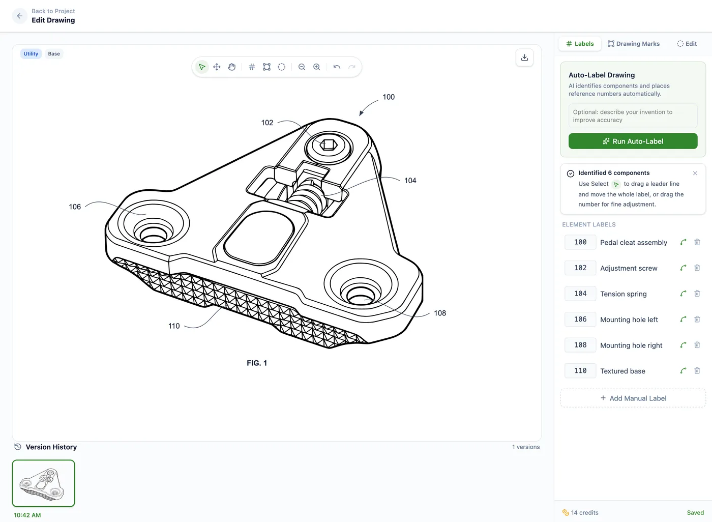
AI limitations in mechanical drawings
PatentDrawingAI works best from clear source images, product photos, sketches, or CAD renders exported as images. It does not edit CAD geometry directly or replace claim-scope judgment. Complex mechanisms may still need additional source views, detail figures, or attorney review before filing.
Generate Mechanical Patent Drawings in Minutes
Upload a CAD render exported as an image, a clear sketch, or a product photo. Generate each needed mechanical figure, add reference numerals and drawing marks, assemble formal sheets, and export a filing-ready drawing set.
Try It Free, No Credit Card RequiredFrequently Asked Questions
Mechanical patents often need more drawing sheets than diagram-only filings because the application may need perspective views, sections, exploded views, detail views, and motion figures. A simple bracket or fastener may need only a few sheets, while a gearbox or linkage can require many more. The guiding principle from 37 CFR 1.84 is to include as many views as necessary to show the invention clearly.
A cross-section cuts through the device and shows internal geometry. An exploded view separates components to show how they fit together. Many mechanical applications need both, but the right test is whether the view helps disclose the claimed structure without crowding the drawing.
Not always. If motion range is simple and obvious (e.g., a lever rotating 90°), you can show both positions in a single figure using phantom lines. For complex, multi-step mechanisms, separate figures at each key position are clearer and less ambiguous. Use your judgment: if a single figure with phantom lines would be confusing, use multiple figures.
The USPTO rules focus on clarity, reproducibility, and avoiding ambiguity. Use section hatching only where it helps explain cut material, keep patterns consistent, and add a legend if a pattern would otherwise be unclear. Do not rely on color unless the application type and filing rules allow it.
Not necessarily. Patent drawings show design geometry and functional relationships. Detailed dimensions and tolerances belong in manufacturing drawings, not patent drawings. Only include tolerances in your patent drawing if they are critical to the patent claims. For example, a claimed gap of 0.5 +/- 0.1 mm should be clear from the disclosure. Otherwise, rely on the written specification to explain functional requirements.
Related Resources
- Utility Patent Drawings : line art, reference numerals, and hatching conventions across utility filings.
- Patent Drawing Examples : 40+ real granted U.S. patents, with mechanical walkthroughs.
- Best Patent Drawing Software in 2026 : ranked tools with mechanical workflow notes.
- How to Make Patent Drawings : the step-by-step workflow from sketch to filing-ready figures.
- Patent Drawing Types: Resource Hub : every drawing-type guide in one place.