In This Guide
If you've ever looked at a patent and wondered why the drawings have such a particular style (thin black lines, no shading, those tiny numbered callouts), there's a reason. The USPTO publishes a single rule, 37 CFR 1.84, that governs every patent drawing in every U.S. application. The rule is short. The interpretations are not.
This guide walks through 40+ real patent drawing examples across utility, design, mechanical, electronic, medical, and software inventions. Every example is a granted U.S. patent you can pull up on Google Patents in two clicks. For each one, we show what the drawing did right, where it fits inside §1.84, and what you'd need to replicate the same compliance level in your own application.
If you'd rather skip the manual work entirely, you can upload a sketch or photo and get USPTO-style drawings in a few minutes. But it helps to know what good looks like first.
What Makes a "Good" Patent Drawing
The USPTO doesn't grade drawings on artistic merit. It grades them on whether the Office of Patent Application Processing (OPAP) can scan, reproduce, and publish them. That's it. The rules in §1.84 exist to make scanning predictable.
Here's the short version of what every formal patent drawing has to satisfy:
| Requirement | The actual rule | Source |
|---|---|---|
| Paper size | 21.0 × 29.7 cm (A4) or 21.6 × 27.9 cm (8½ × 11"). All sheets must be the same size. | §1.84(f) |
| Margins | Top ≥ 2.5 cm, left ≥ 2.5 cm, right ≥ 1.5 cm, bottom ≥ 1.0 cm. Sight no greater than 17.0 × 26.2 cm on A4 or 17.6 × 24.4 cm on letter. | §1.84(g) |
| Lines | Black, durable, clean, sufficiently dense, uniformly thick, well-defined. India ink or equivalent. | §1.84(l) |
| Reference characters | At least 0.32 cm (1/8 inch) tall. Plain, legible, not enclosed in brackets or outlines. | §1.84(p)(1), (p)(3) |
| Hatching | Regularly spaced oblique parallel lines, "preferably 45°." Different elements get different angles. | §1.84(h)(3) |
| Solid black shading | Not permitted — except for bar graphs or to represent the color black. | §1.84(m) |
| Color | Black-and-white only, unless you file a color-drawing petition under §1.84(a)(2) with the §1.17(h) fee. | §1.84(a)(1)–(2) |
| Sheet numbering | Format X/Y (e.g., 1/3, 2/3) centered at the top, inside the sight, larger than reference numerals. | §1.84(t) |
| View labels | FIG. 1, FIG. 2, etc. Partial views share a number with a letter (FIG. 1A, 1B). Larger than reference numerals. | §1.84(u) |
The simplest test: if you reduced your drawing to 2/3 size on a black-and-white photocopier, would every line, numeral, and feature still be legible? If yes, you're probably compliant. If no, you have work to do — §1.84(k) requires drawings to remain readable at 2/3 reduction.
Now let's look at how those rules show up in real granted patents.
Utility Patent Drawing Examples
Utility patents protect how something works. The drawings have to show the structural relationships between every claimed element. That usually means at least one perspective view, plus enough orthogonal views (front, side, top, bottom) to show every claimed feature, plus cross-sections or exploded views where the internal structure matters. For a deeper walkthrough, see our utility patent drawings guide.
Perspective and Isometric Views
Perspective views are usually the first figure of a utility patent. They give the examiner an immediate three-dimensional sense of the invention before the orthogonal views and cross-sections drill into specifics.

Bell's telephone (US 174,465)
View original on Google Patents
One of the most famous patents in U.S. history. Look at how Bell's drawing uses simple perspective lines, no shading, and reference characters tied to a single description. Even by 1876 standards the drawing follows the conventions that became §1.84 — one shorter side at the top, consistent line weight, plain numerals, and a reference-character key in the specification rather than on the drawing itself.

The Wright Brothers' flying machine (US 821,393)
View original on Google Patents
Notice how the Wrights used a perspective view as Figure 1, then broke the same machine down into orthogonal side, top, and front views in subsequent figures. That's still the standard sequence today: one figure for context, more figures for precision. The reference numerals (1, 2, 3, 4 …) are in the same plain Arabic style §1.84(p)(1) requires now.

Stanford / Google's PageRank algorithm (US 6,285,999)
View original on Google Patents
A pure software invention with no physical embodiment — yet it still uses drawings. Figure 1 is a network-graph perspective; Figure 4 is a flowchart. Both qualify as "drawings" under §1.84 because they illustrate the claimed method. The lesson: perspective views aren't only for hardware, and a clean directed graph beats a screenshot every time.
Orthogonal Views — Front, Side, Top, Bottom
Orthogonal (or "elevation") views give the examiner exact dimensional and proportional information. §1.84(h) lets you use as many or as few as you need to show the invention, but they have to be projected consistently — top view above front view, right side to the right of front view, and so on.

The original LEGO brick (US 3,005,282)
View original on Google Patents
The LEGO patent is a textbook example of orthogonal projection. A perspective in Figure 1, a side elevation, a bottom plan view, and a vertical cross-section. Notice the cross-section uses 45° hatching with consistent spacing — exactly the convention §1.84(h)(3) recommends. Reference numerals are external to the drawing with lead lines pointing in.

Dyson's vacuum cleaning appliance (US 4,373,228)
View original on Google Patents
The foundational Dyson cyclone patent. The figures use only the views needed to disclose the cyclonic flow path — a side cross-section showing airflow arrows, an exploded perspective, and a top plan. No solid black shading anywhere; airflow direction is shown with simple arrows tied to reference characters in the specification.
Cross-Sectional Views
Cross-sections expose internal structure that an elevation view can't. §1.84(h)(3) is specific about how they have to be drawn: "regularly spaced oblique parallel lines… preferably 45°." Different juxtaposed parts get hatched at different angles or with different patterns so the examiner can tell them apart.

Edison's incandescent lamp (US 223,898)
View original on Google Patents
The whole patent is essentially a single longitudinal cross-section showing the bulb interior. Look closely at the 45° hatching on the glass envelope versus the cross-hatching on the metal base — different angles for different materials. This convention from 1880 is still how mechanical engineers indicate material differences in 2026 drawings.
Exploded Views
Exploded views show how components fit together. They're not required, but they make assemblies dramatically easier for an examiner to understand than trying to label every part on a single perspective drawing. §1.84(h)(2) explicitly permits them when "necessary" for clarity, and they should use a "bracket" or projection lines to show alignment.

The original iPhone multi-touch patent (US 7,479,949)
View original on Google Patents
This utility patent uses exploded perspectives plus signal-flow block diagrams. Figure 1 is a system overview; Figures 4–6 show the gesture-recognition logic in flowchart form. Note that the figures use no solid black except where a finger or contact area is shown, and all reference numerals stay outside the figure body.
Design Patent Drawing Examples
Design patents protect how something looks. The rules under 37 CFR 1.152 and MPEP §1503.02 are different from utility patents in three important ways:
- Surface shading is encouraged. §1.152 says "appropriate and adequate surface shading should be used to show the character or contour of the surfaces represented." Solid black is still off-limits except to represent the color black.
- Broken lines have a special meaning. They show "visible environmental structure" — context that's not part of the claimed design. They cannot be used for hidden surfaces, and they cannot show alternate positions in the same view.
- Color drawings are permitted without a petition. Per §1.84(a)(2), color is allowed in design applications outright (you still need to follow the §1.84(a)(2)(ii)–(iii) submission rules).
For the complete walkthrough of design-patent figures, see our design patent drawings guide.

The iPhone design patent (USD 618,677)
View original on Google Patents
The textbook example of design-patent drawings. Seven views: front, rear, top, bottom, left side, right side, and a perspective. Surface contours are shown with light stippling (a permissible alternative to line shading). Notice the broken lines around the screen bezel — they represent unclaimed environmental surfaces, allowing the patent to claim only the claimed visual element.

The Statue of Liberty design patent (USD 11,023)
View original on Google Patents
One of the oldest design patents in the U.S. system. Bartholdi used a single front elevation, with surface shading to convey the contour of the figure. Even though the document is from 1879, the use of consistent line weight and the absence of dimensional callouts maps directly onto the modern §1.152 standard.
Example 10 — Athletic Shoe Outsole DesignsBrowse examples via Google Patents design search
Athletic shoe outsole patterns (design patent convention)
View original on Google Patents
Outsole design patents show how to claim surface-ornamentation patterns under §1.152. The drawings typically use dense stippling to convey foam or rubber texture without falling into the prohibited "solid black" zone, with broken lines marking the unclaimed upper of the shoe. Browse the design search for "shoe outsole" to see dozens of approved examples from Adidas, Nike, New Balance, and others.
The 2026 GUI/icon update
The USPTO's Supplemental Guidance for Computer-Generated Interfaces and Icons, effective March 13, 2026, removed the prior MPEP §1504.01(a) requirement that a screen or article of manufacture be shown in solid or broken lines for GUI/icon design applications. If you're filing a design patent on a software interface, you no longer need to draw the laptop or phone surrounding it as long as the title and claim properly identify the article of manufacture. This is a meaningful simplification.
Mechanical Invention Examples
Mechanical inventions are where the §1.84 rules came from in the first place. The drawing has to clearly show every claimed structural feature — its shape, its relationship to other features, and how it operates. The most common views you'll see in granted mechanical patents are perspective, exploded, cross-section, and assembly.

The original Nike Air sole (US 4,219,945)
View original on Google Patents
Frank Rudy's gas-filled footwear sole patent. Uses a perspective view (Figure 1) followed by multiple longitudinal and transverse cross-sections to disclose the air-chamber structure. Hatching density is kept low — readable, not overwhelming. Reference numerals point only to features mentioned in the specification, complying with §1.84(p)(5).

The Nova Cruz / Xootr folding scooter (US 6,443,470)
View original on Google Patents
The folding-scooter patent originally assigned to Nova Cruz Products and later transferred to Xootr LLC. (Razor scooters were a separate product line with their own IP.) Multiple figures show the scooter in folded and unfolded states, with enlarged details of the folding mechanism and steering geometry. A textbook approach for a mechanism with a moving subassembly — show it in two states, then enlarge the joint that performs the motion.

The EpiPen origin patent (US 4,031,893)
View original on Google Patents
Sheldon Kaplan's auto-injector patent at Survival Technology that became the EpiPen platform. Multiple longitudinal cross-sections show the spring and needle in pre-fire and post-fire states, plus an enlarged detail of the variable-medicament-capacity mechanism. Cross-sections use different hatching angles for the metal and plastic components — a clean application of §1.84(h)(3) about distinguishing juxtaposed elements.
For a deeper walkthrough of mechanical drawing conventions — including which views are typically required, hatching patterns for different materials, and how to handle assemblies with hundreds of parts — see our utility patent drawings guide.
Electronic and Circuit Patent Examples
Electronic patents present a specific challenge: schematics use text-heavy labels, but §1.84(p)(5) limits text in drawings to reference characters. The workaround, sanctioned by the MPEP, is to show schematic elements with standard symbols and use reference numerals — not part numbers — for callouts. MPEP §608.01(p) permits "a few descriptive words" inside the drawing where they "form an integral part of the drawing or aid in reading it."

Noyce's integrated circuit (US 2,981,877)
View original on Google Patents
The patent that helped launch Silicon Valley. Figure 1 is a perspective view of the IC; subsequent figures cross-section the layered structure. Reference numerals identify each functional region. Worth studying for how to disclose a multi-layer device in a single, scannable drawing.
Example 15 — Wireless / Communications Block DiagramsBrowse examples via Google Patents
Block-diagram conventions for electronics patents
View original on Google Patents
Block diagrams are the workhorse of electronics patents. Each functional block is a labeled rectangle; signal lines connect them. The labels themselves are short — "MODULATOR," "ANTENNA," "PROCESSOR" — exactly the kind of "few descriptive words" §608.01(p) permits. Reference numerals sit outside the blocks and connect with short lead lines.
Electronic patent drawings have their own conventions for continuation labels ("TO FIG. 2B CONT."), printed circuit board (PCB) drawings, and IEEE/ANSI schematic symbols.
Medical Device Examples
Medical device patents often combine mechanical features (a delivery mechanism), anatomical context (broken-line outlines of tissue), and sometimes photographs (for histological sections, where photos are explicitly permitted under §1.84(b)). The drawings have to disclose every claimed structural element while staying within the formatting rules.
Medical device convention — anatomical context in broken lines
Medical device drawings combine mechanical and anatomical conventions
Medical device patents typically combine mechanical features (a delivery mechanism, a housing, a needle) with anatomical context shown in broken lines. The convention: claimed device structure is drawn in solid lines per §1.84(l); patient anatomy or surrounding tissue is drawn in broken lines (unclaimed environment), the same way design patents handle environmental context. For surgical instruments, scopes, and implantables, this lets the figures show "where the device goes" without claiming the surrounding tissue. The EpiPen example above (US 4,031,893) is one application; browse Google Patents for "endoscope" to see anatomical-context conventions in surgical-instrument patents.
Software, Method, and Algorithm Examples
Post-Alice software patents have made flowcharts and block diagrams the de-facto required visualization for method claims. The drawings still have to comply with §1.84 — same line weight, same numeral height, same paper size — but the conventions for what to draw are different from hardware patents.

Facebook News Feed (US 7,669,123)
View original on Google Patents
A pure software patent — the canonical Facebook News Feed patent (Zuckerberg et al.). Figures 1–3 are system architecture diagrams (servers, data stores, clients) shown as labeled rectangles. Subsequent figures are flowcharts showing the ranking method. Each step is a labeled box with directional arrows. Reference numerals identify the functional blocks for cross-reference in the specification.

Amazon "1-Click" purchasing (US 5,960,411)
View original on Google Patents
The original 1-Click patent (now expired). The flowcharts have become a teaching example for method-claim drawings. Each block represents a discrete step; arrows show flow. The use of decision diamonds (yes/no branches) makes the method's logic immediately obvious to an examiner who can't run the code.
For pure-software patents, you generally need: a system architecture diagram (showing the components that perform the method), a flowchart for each independent method claim, and any data structures the claims reference. That's typically 4–8 figures total.
More Verified Examples Worth Studying
A short list of additional granted patents — every number below has been individually verified against Google Patents. Click any patent to load the full drawings.
| Patent | Subject | What to study |
|---|---|---|
| USD 504,889 | Apple iPod design | Seven-view design-patent layout |
| USD 683,268 | Tesla Motors · Model S "Vehicle" design | Vehicle design patent — multiple elevations plus a 3/4 perspective |
| US 6,883,201 | iRobot · Autonomous Floor-Cleaning Robot (Roomba) | Sensor-mapped robot using top-plan and perspective views |
| US 4,405,829 | Rivest, Shamir, Adleman · RSA "Cryptographic communications system and method" | Mathematical algorithm rendered as a flowchart plus data-flow diagrams |
For more verified historical examples, the USPTO Patent Public Search and Google Patents are the two best free resources. We recommend pulling up patents in your own field rather than relying on a one-size-fits-all list — the conventions vary by industry.
Before and After: PatentDrawingAI Examples
Real patent examples show the destination. These before-and-after examples show the starting point most inventors actually have: a photo, a rough sketch, or a CAD-style render.
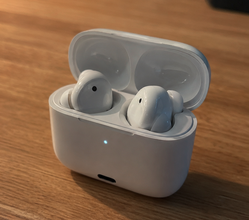
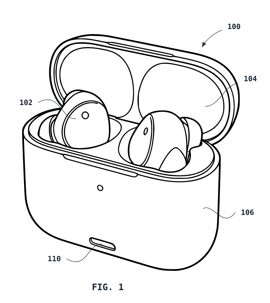
Photo of earbuds to patent-style line drawing
The input photo includes color, lighting, shadows, background texture, reflections, and perspective distortion. The PatentDrawingAI output strips that down to patent-style linework with external reference numerals and lead lines.
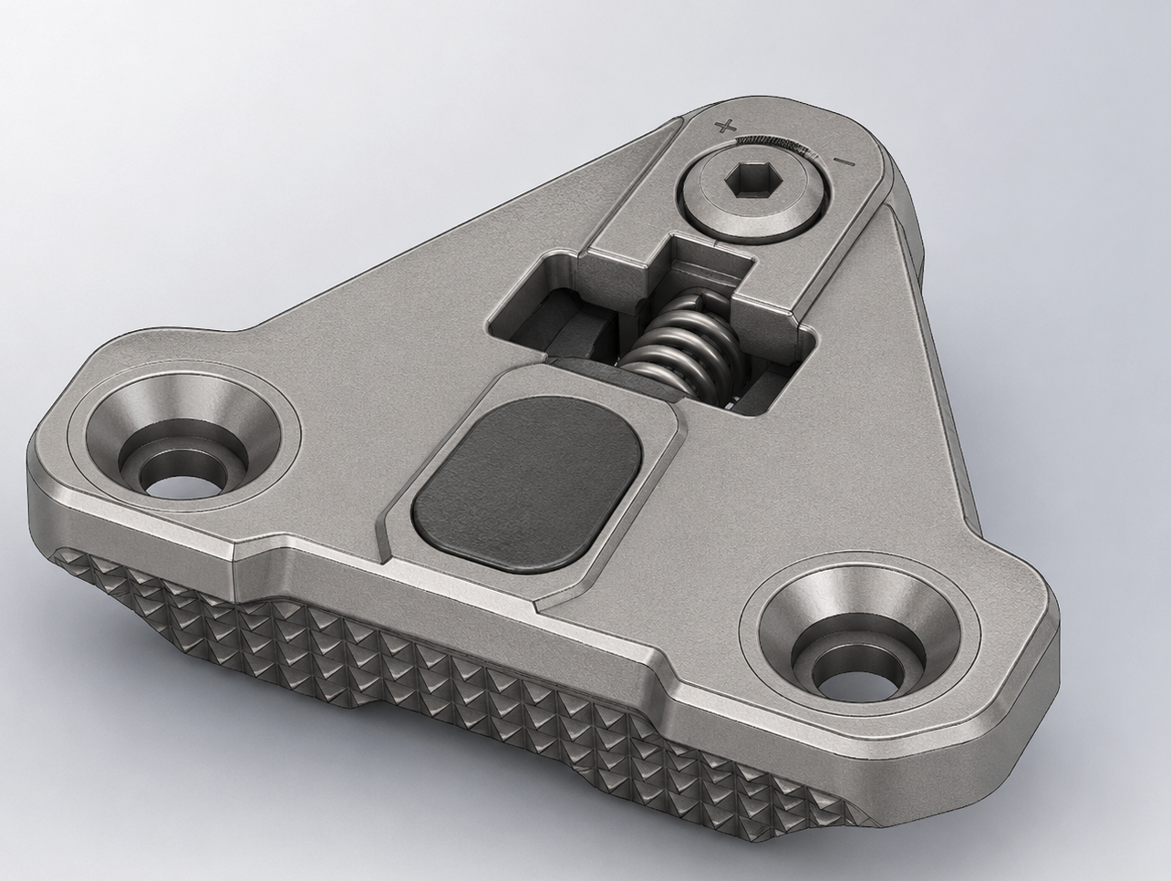
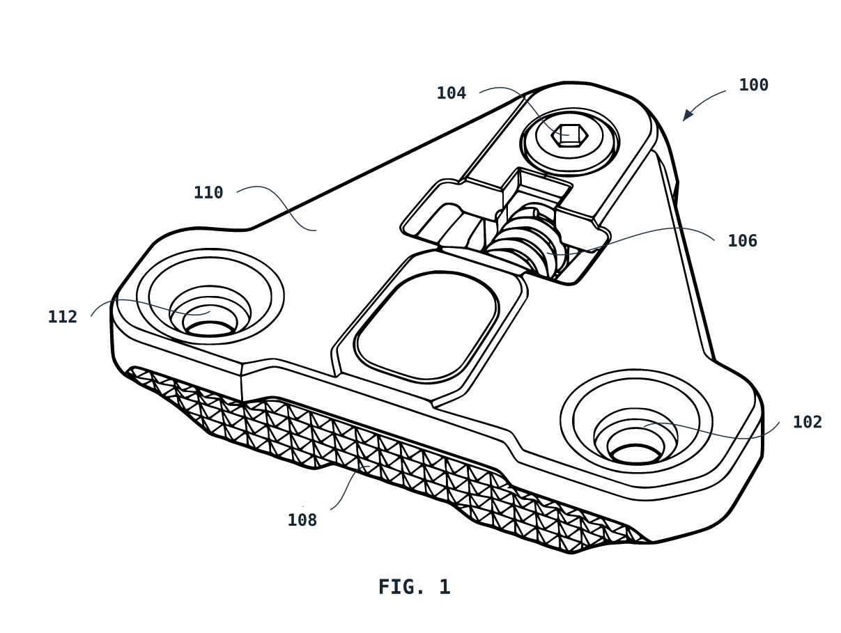
CAD-style render to clean utility drawing
The input render communicates material and realism. The patent-style output communicates structure: holes, spring area, textured edge, surface boundaries, and numbered features.
Rough sketch to consistent line drawing
The sketch already has the key idea, but it also has graph paper, construction lines, uneven darkness, and ambiguous edges. The AI output keeps the recognizable structure while producing cleaner lines and consistent reference-number placement.
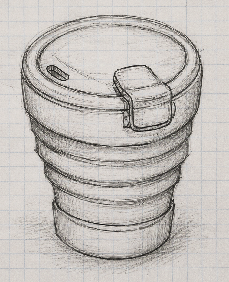
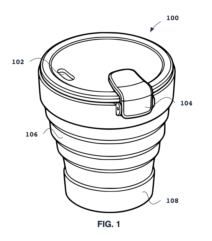
The shortcut: tools like PatentDrawingAI automate this exact translation. You upload the sketch, photo, or CAD render and the AI produces a §1.84-compliant PDF, PNG zip, or SVG zip in a few minutes. You can then refine line weight, shading, and broken-line treatment in the editor before exporting. Useful when you're filing more than one or two patents a year and want to skip the 3-to-10-day illustrator turnaround.
Why Drawings Get Rejected (and How to Avoid It)
OPAP reviews every drawing for whether it can be scanned and reproduced for publication. The standard is forgiving — MPEP §608.02(b) says most drawings, "including those that have been indicated by applicant to be 'informal drawings,' will be acceptable." When OPAP does object, it issues a Notice to File Corrected Application Papers with a 2-month period to fix the issue.
The most common issues that trigger a Notice:
Top OPAP rejection reasons
- Reference numerals smaller than 1/8 inch (0.32 cm). Per §1.84(p)(3) — non-negotiable.
- Solid black shading. Prohibited by §1.84(m) except for bar graphs or to represent the color black.
- Color drawings filed without a §1.84(a)(2) petition. Color is not allowed in utility applications without a petition + fee.
- Photographs filed without justification under §1.84(b). Photos are only allowed when they're the only practicable medium.
- Out-of-spec margins. §1.84(g): top ≥ 2.5 cm, left ≥ 2.5 cm, right ≥ 1.5 cm, bottom ≥ 1.0 cm.
- Sheet numbering missing or misplaced. §1.84(t) requires X/Y format centered at the top of each sheet, inside the sight.
- Drawing sheets not labeled "Replacement Sheet" or "New Sheet" when filed after the application date. Required by §1.121(d).
- Faded or low-contrast lines that cannot be cleanly scanned. §1.84(l) requires "durable, clean, black… sufficiently dense and dark."
For the full list, see MPEP §507 on USPTO papers review and MPEP §608.02 on drawing standards.
Pre-Filing Checklist
Before you submit drawings to the USPTO Patent Center, run them through this checklist. Every line is anchored to a specific rule.
- Sheet size is 21.6 × 27.9 cm (8½ × 11") or 21.0 × 29.7 cm (A4) — and all sheets are the same size [§1.84(f)]
- Margins are at least: top 2.5 cm, left 2.5 cm, right 1.5 cm, bottom 1.0 cm [§1.84(g)]
- Sight is no greater than 17.0 × 26.2 cm (A4) or 17.6 × 24.4 cm (US letter) [§1.84(g)]
- All lines are durable, clean, black, sufficiently dense, uniformly thick [§1.84(l)]
- Reference numerals are at least 0.32 cm (1/8 inch) tall [§1.84(p)(3)]
- Reference numerals are plain Arabic, not enclosed in brackets, and don't appear on hatched/shaded surfaces [§1.84(p)(1)]
- Every reference numeral mentioned in the description appears in the drawings — and vice versa [§1.84(p)(5)]
- Each reference numeral has a lead line connecting it to its feature [§1.84(q)]
- Hatching is regularly spaced parallel lines, preferably at 45° [§1.84(h)(3)]
- No solid black shading — except for bar graphs or to represent color black [§1.84(m)]
- Sheet numbering is X/Y format, centered at the top, larger than reference numerals [§1.84(t)]
- View labels are FIG. 1, FIG. 2, etc. (or FIG. 1A, 1B for partial views) and larger than reference numerals [§1.84(u)]
- Drawings remain legible if reduced to 2/3 size [§1.84(k)]
- File is uploaded as a PDF (≤ 25 MB) to Patent Center; if you've exported as a raster image, ensure it's 300 DPI minimum, black-and-white, and embedded in a PDF before upload [USPTO Patent Center file rules]
Generate USPTO-style drawings from a sketch in minutes
Upload a sketch, photo, or CAD render. PatentDrawingAI produces §1.84-formatted line drawings — correct margins, line weight, reference numerals, hatching — in a few minutes. Refine in the editor. Export as PDF, PNG zip, or SVG zip.
Try It FreeFrequently Asked Questions
Related Reading
- Best Patent Drawing Software in 2026 — full comparison of AutoCAD, Visio, Illustrator, SmartDraw, and AI-native tools
- Utility Patent Drawings: Complete Guide — what utility drawings actually require
- Design Patent Drawings: Complete Guide — seven-view layout, surface shading, and §1.152 specifics
- USPTO Patent Drawing Requirements — full §1.84 compliance reference
- How to Make Patent Drawings (Step-by-Step Guide)
- Patent Drawing Types Hub — every patent drawing topic on the site