Understanding 37 CFR 1.84
37 CFR 1.84 is the USPTO regulation that sets the formal standards for patent drawings. It covers the drawing sheet, margins, line quality, lettering, reference characters, views, shading, photographs, color drawings, and replacement sheets.
The related rules matter too. 37 CFR 1.83 says drawings in a nonprovisional application must show every claimed feature where drawings are used. MPEP 608.02 explains how the Office handles drawing requirements and corrections. For design applications, 37 CFR 1.152 adds the sufficient view and surface-shading rules that define the visual disclosure.
Why 37 CFR 1.84 matters
Drawing objections are usually fixable, but they consume time and can force replacement sheets. A source-backed drawing checklist reduces preventable objections before filing and helps keep the drawings, claims, and specification aligned.
Paper Size and Margin Specifications
37 CFR 1.84 allows A4 or U.S. letter-size drawing sheets. Every sheet in the application must use the same size, and the usable drawing area must stay inside the required margins.
Accepted Paper Sizes
- U.S. letter: 21.6 cm x 27.9 cm (8.5 in x 11 in)
- International: 21.0 cm x 29.7 cm (ISO 216 A4 size)
- Paper quality: flexible, strong, white, smooth, non-shiny, durable paper with only one side used
Margin requirements
| Margin Position | Inch equivalent | CFR minimum |
|---|---|---|
| Top Margin | 1 in minimum | 2.5 cm |
| Bottom Margin | 3/8 in minimum | 1.0 cm |
| Left Margin | 1 in minimum | 2.5 cm |
| Right Margin | 5/8 in minimum | 1.5 cm |
Practical margin buffer
The rule states minimum margins. In production, leave a small buffer beyond the minimum so scaling, export settings, and PDF conversion do not push line art into the margin area.
Line Quality Requirements
Line quality is a reproduction issue. Drawings must be dark, clean, and reproducible enough that the Office and the public can understand the invention after copying or reduction.
Ink and Color Specifications
- Black drawing lines: Use black line work unless a color-drawing petition is allowed under 37 CFR 1.84(a)(2)
- Permanent, reproducible marks: The rule is written for paper drawings, but the same practical point applies to digital exports: the line work must stay clear when reproduced
- No pencil or light lines: Pencil sketches or light lines that are hard to see may require correction
Line Density and Weight
- Uniform thickness: Lines should be consistently thick, not thin and wispy. Thin lines disappear when drawings are photocopied or reduced
- Dense and dark: Lines must be sufficiently dark and dense to reproduce clearly at 2/3 reduction (the standard copying size for patent office submissions)
- Well-defined: No fuzzy edges, broken lines, or uneven strokes. Lines should have crisp, clean edges
- Practical line weight: choose a line weight that stays visible after reduction and does not obscure small features
What Gets Rejected
- Thin lines that fade when photocopied
- Inconsistent line weight across the same drawing
- Broken or interrupted lines (unless intentionally dashed)
- Gray lines or watercolor shading (not permitted; use cross-hatching instead)
Reference Numeral Rules
Reference numerals are the numbered labels that identify features in the drawings and tie those features back to the specification. In a nonprovisional application, 37 CFR 1.83 requires the drawings to show every claimed feature when drawings are used.
Size and Appearance Requirements
- Minimum height: 0.32 cm (1/8 inch), this is the absolute minimum. Smaller numerals may be rejected
- Practical height: Larger, consistent labels are often easier to read than labels placed exactly at the minimum
- Font: Use a plain, legible style
- Avoid decorative styles: Ornate fonts are harder to read when reduced
- No special fonts: Avoid script, cursive, or decorative fonts
Placement and Lead Line Rules
- Lead lines: Use leader lines where needed to make the connection between a reference character and a feature clear
- Lead line style: Lead lines are typically solid thin lines or arrows. They should point clearly to the component without ambiguity
- Avoid overcrowding: Numerals should not overlap with other numerals, components, or hatching. If space is tight, use a leader with an arrow and place the numeral outside the drawing area
- Placement orientation: Numerals should be oriented horizontally when possible for maximum readability
- Consistency: All numerals should be the same size and style throughout the drawing set
Numbering Convention
- Common convention: Reference numerals often begin at 10 and increment by 10 (10, 20, 30, 40) to allow room for additions without renumbering
- Avoid confusion: Keep reference numerals distinct from figure numbers, sheet numbers, and section labels
- Consistency across all sheets: Each component retains the same reference numeral throughout all drawing sheets. If component 20 is the motor in FIG. 1, it is also 20 in FIG. 2
- Claim support: If a claim recites a feature and drawings are needed to understand it, the drawings should show that feature clearly
View Requirements and Figure Types
The number of views depends on what the invention needs to disclose. Utility drawings should show the claimed features clearly. Design drawings must include enough views to disclose the appearance of the claimed design under 37 CFR 1.152.
Common View Types
Perspective (3D) View
An isometric or 3D representation showing the overall shape and appearance. Usually FIG. 1. Gives immediate visual understanding of the invention's form factor.
Orthographic Views
Standard engineering views: front elevation, rear elevation, top plan, bottom plan, left side, right side. Each view shows details hidden in others from a different angle.
Cross-Sectional Views
Slice through the invention to show internal structure, layering, or hidden mechanisms. Indicated with a cutting line in the main view (usually labeled "Section AA") and the corresponding cross-section labeled accordingly.
Exploded Views
Components separated along assembly axes to show how they fit together. Essential for multi-part mechanical inventions. Dashed lines or arrows indicate relationships between separated parts.
Detail Views
Enlarged views of small or complex features. A circled area (often marked as a detail reference) in a main view is expanded to show fine detail at larger scale. Labeled as "Detail A–A" or similar.
Flowcharts and Block Diagrams
For software, method, and process patents. Show sequence of steps, decision points, data flow, and logical relationships. Each block or symbol labeled with a reference numeral.
View Labeling Convention
- Figure labels: Each view is labeled as FIG. 1, FIG. 2, FIG. 3, etc. (or Fig. 1, Fig. 2; format is flexible but must be consistent)
- Numbering sequence: Figures are numbered consecutively across all sheets. FIG. 1 might be on Sheet 1, FIG. 2 on Sheet 1, FIG. 3 on Sheet 2, etc.
- Descriptive legends: Brief legends may be used when they help explain the view, subject to USPTO approval
- Location of labels: Figure labels typically appear below the figure, centered or near the bottom of the drawing area
Arrangement of Multiple Views on a Sheet
- Arrange views logically. Put primary views where they are easy to scan and keep detail views close to the feature they explain
- Leave adequate white space between views to prevent visual confusion
- Keep orientation consistent when possible so the reader does not need to rotate the sheet unnecessarily
- If using multiple view types (e.g., perspective + orthographic), keep them visually distinct and well-separated
Shading, Hatching, and Material Conventions
Shading and hatching help explain shape and structure. They must stay line-based, legible, and consistent with what the drawing is meant to disclose.
Cross-Hatching for Cross-Sections
- Indicates cut surfaces: Where you "cut" through a material in a cross-section view, the exposed surface is filled with cross-hatching
- Pattern style: Evenly spaced parallel lines at 45 degrees is the standard. Spacing should be consistent and fine enough to be legible when reduced
- Different materials, different patterns: You may use different cross-hatch patterns or densities to indicate different materials (e.g., dense hatching for metal, lighter hatching for plastic)
- Avoid solid fills: Do not use solid black fills for cross-sections; always use line-based hatching
Surface Shading for 3D Form
- Purpose: Shading shows curved surfaces and 3D contours in perspective views. It gives depth and helps visualize the shape
- Technique: Spaced parallel lines (stippling or fine line shading) to show curved surfaces. Density increases toward shadow areas
- No solid gray: Never use solid gray fill. Always use line-based shading (stippling or line patterns)
- Subtle and controlled: Shading should enhance clarity, not dominate the drawing. It should never obscure detail or make the drawing harder to read
Material Indication
- Cross-hatch patterns indicate material type: Use distinct patterns only when they help the reader understand the drawing. Keep the convention consistent throughout the set
- Consistency required: If you use a hatching pattern to indicate material, use the same pattern wherever that material appears throughout the drawing set
- Legend: A short legend can help when the drawing uses multiple hatching conventions
Broken Lines for Environment or Context
- Dashed or broken lines: In design drawings, broken lines may show visible environmental structure or unclaimed subject matter. They should not obscure the claimed design
- Clarity: Broken lines should be clearly distinct from solid lines so the reader can tell claimed subject matter from environment or context
Text, Legends, and Labels
Patent drawings should communicate visually. Use text only where the drawing rules permit it or where the Office requires a legend for understanding.
Permitted Text
- Figure labels: FIG. 1, FIG. 2, etc. (placed below each figure)
- Reference numerals: 10, 20, 30, etc. (used to connect drawing features to the specification)
- Brief legends: Short labels like "View AA," "Detail B-B," or "Side View" when they clarify the drawing
- Material or process indicators: Brief notes may be used sparingly where a legend is necessary
- Section line labels: "AA," "BB," "CC" etc. to indicate where a cross-section is taken
Forbidden Text
- Descriptive matter: Avoid narrative explanations of how the invention works. Put that in the specification
- Component names or function descriptions: Avoid labels like "Motor," "Bearing," or "Drive Shaft" when reference numerals and the specification can do that work
- Claims or claim language: Do not paste claim text into the drawings
- Lengthy explanations: No paragraph-style text explaining features
Text Formatting in Drawings
- Font size: Text must be clear and legible at all times, especially when reduced for reproduction
- Font style: Use standard sans-serif font (Arial, Helvetica, etc.). Avoid script, cursive, or decorative fonts
- Black text only: Text must be black, not gray or any other color
- Orientation: Text should be oriented horizontally for maximum readability. Vertical or sideways text should be avoided unless absolutely necessary
Sheet Numbering and Figure Numbering
Patent drawings are submitted as a set of numbered sheets, and each view on those sheets is a numbered figure. Proper numbering is essential for clarity and compliance.
Sheet Numbering
- Format: Each sheet is numbered as "X/Y" where X is the current sheet number and Y is the total number of sheets. For example, if you have 5 sheets of drawings, they are labeled "1/5," "2/5," "3/5," "4/5," "5/5"
- Placement: Sheet numbers typically appear in the bottom right corner of each sheet
- Size: Sheet numbers should be legible but smaller than reference numerals, typically 0.6–0.8 cm in height
- Consistency: All sheet numbers must follow the same format and placement
Figure (View) Numbering
- Sequential numbering: Figures are numbered consecutively across all sheets: FIG. 1, FIG. 2, FIG. 3, etc. (not restarting on each sheet)
- Labeling format: "FIG. 1" or "Fig. 1" (capitalization and punctuation should be consistent throughout)
- Multiple views on one sheet: If Sheet 1 contains FIG. 1, FIG. 2, and FIG. 3, then Sheet 2 begins with FIG. 4
- Placement: Figure labels appear below each figure, typically centered or slightly to one side
- Size: Figure labels should be larger than reference numerals but smaller than main drawing lines, typically 0.5–0.8 cm in height
Relationship Between Drawings and Specification
- Consistency: Every figure referenced in your specification must appear in the drawings. If your specification says "as shown in FIG. 3," FIG. 3 must exist and match the description
- Claim support: Features recited in the claims should be shown and described consistently when the drawings are needed to understand them
- Order: The figure order should generally follow the narrative flow of the specification
Special Rules: Color, Photographs, and CAD Workflows
Black-and-white line drawings are the default. Color, photographs, and CAD-prepared drawings each have separate filing considerations.
Color Drawings
- Default rule: Use black-and-white line drawings unless color is necessary to disclose the subject matter
- When color is permitted: Color drawings can be submitted only when the petition and statement under 37 CFR 1.84(a)(2) show that color is the only practical medium for the disclosure
- Petition requirements: A formal petition must accompany the color drawings, along with the applicable petition fee
- Required statement: the specification must include the color-drawing statement required by the rule
- Practical note: if color is not essential, convert the drawing to black-and-white line art before filing
Photographs
- Default rule: Photographs are not the normal format for utility or design drawings
- Exception: 37 CFR 1.84(b) permits photographs when the subject matter cannot be shown adequately in an ink drawing
- Examples: the rule points to subject matter such as crystalline structures, metallurgical microstructures, electrophoresis gels, and similar cases
- Quality requirements: Photographs must be sharp, clear, well-lit, and capable of reproduction at 2/3 reduction size
- Color photographs: color still requires the color-drawing requirements when color is the disclosure medium
CAD-prepared drawings
- Digital preparation: CAD tools can be used to prepare source views, but the final drawing must still comply with the USPTO drawing rules
- File format: native CAD formats like .dwg or .step are not themselves the filing-ready drawing set. Export the views into the filing workflow your application uses
- Resolution and quality: exported images must remain clear, dark, and reproducible
- Compliance required: CAD-generated drawings must comply with all 37 CFR 1.84 specifications, including margins, line quality, and reference numerals, just as hand-drawn or illustrated versions
Application Type and Drawing Expectations
The drawing standard depends on the application context. A provisional sketch, a utility nonprovisional drawing set, and a design patent drawing each carry different practical risks.
| Application context | Drawing standard | Practical note |
|---|---|---|
| Utility nonprovisional | Drawings must satisfy 37 CFR 1.84 formatting, and 37 CFR 1.83 requires the drawings to show every claimed feature where drawings are used. | Best practice is to prepare formal drawings before filing so the specification, claims, and figures support each other from the start. |
| Design patent | 37 CFR 1.152 requires a sufficient number of views to disclose the appearance of the design, with surface shading where needed. | Broken lines, surface shading, and omitted views affect claim scope, so design drawings need extra care beyond basic sheet formatting. |
| Provisional application | A drawing is required when necessary to understand the subject matter. Formal drawing objections usually matter later when moving into a nonprovisional filing. | Readable informal sketches can establish useful disclosure, but filing-ready drawings reduce redraw work and help avoid gaps in the later application. |
| Amended or replacement drawings | Corrected sheets must follow USPTO replacement-sheet rules and cannot add new matter beyond the original disclosure. | Fix formality problems without changing what the original application disclosed. |
Provisional vs. nonprovisional practice
A provisional application can include informal drawings if they support the disclosure, but those sketches often need to become formal drawings later. PatentDrawingAI helps turn clear sketches, photos, or CAD renders into filing-ready figures and assembled sheets for review before filing. For the filing-date and disclosure details, see the provisional patent drawing requirements guide.
Common Drawing Objections and How to Reduce Them
Drawing problems usually appear as objections or correction requirements, not as a final decision on the invention. The fastest fixes are the ones you catch before filing.
Checklist items to review before filing
1. Incorrect or Insufficient Margins
- Problem: margins that fall short of the CFR minimums: top 2.5 cm, left 2.5 cm, right 1.5 cm, bottom 1.0 cm
- Result: a drawing objection or notice requiring corrected sheets
- How to avoid: Use drawing software with margin settings built-in, or measure carefully if preparing drawings manually. Leave a small buffer beyond the minimum
2. Missing or Improperly Sized Reference Numerals
- Problem: Reference numerals smaller than 0.32 cm (1/8"), or missing numerals for elements mentioned in the claims
- Result: correction may be required before the drawings are accepted for examination
- How to avoid: Use a minimum font size of a size comfortably above 0.32 cm. Keep a master reference list for features shown in multiple views
3. Poor Line Quality
- Problem: Thin, light, or inconsistent lines that disappear when photocopied or reduced
- Result: the Office may require clearer replacement drawings
- How to avoid: Use pen width of 0.6–1.2 mm in drawing software. Test by reducing to 2/3 size and printing to ensure lines remain visible
4. Inadequate or Missing Views
- Problem: Not enough views to fully illustrate the invention. For example, submitting only perspective views when cross-sections are needed to show internal structure
- Result: the Office may require additional illustration or clarification
- How to avoid: Include all views necessary for someone skilled in the art to understand the invention. If your specification describes a feature from a particular angle, show a drawing view of it
5. Incorrect or Missing Figure Labels
- Problem: inconsistent figure labels, missing figure labels, or references in the specification that do not match the drawings
- Result: corrected labeling may be needed
- How to avoid: Use consistent labeling: FIG. 1, FIG. 2, FIG. 3 (or Fig. 1, Fig. 2, Fig. 3, but be consistent). Number sequentially across all sheets
6. Incorrect Sheet Numbering
- Problem: sheets missing consecutive sheet numbering or using inconsistent numbering
- Result: Formality issue requiring correction
- How to avoid: number drawing sheets consecutively as X/Y, such as 1/5, 2/5, and 3/5
7. Use of Color Without Petition
- Problem: Color drawings submitted without a filed petition for color drawings under 37 CFR 1.84(a)(2)
- Result: the Office may require black-and-white drawings or the required petition materials
- How to avoid: use black-and-white line drawings unless color is the only practical disclosure medium
8. Cluttered or Illegible Drawings
- Problem: Too many reference numerals crammed into small areas, or reference numerals overlapping with components or hatching
- Result: clearer replacement drawings may be required
- How to avoid: Use leader lines and callouts to place numerals outside congested areas. Spread out views and use adequate white space
9. Inconsistent Reference Numerals
- Problem: The same component labeled as "20" in FIG. 1 but "25" in FIG. 2, or reference numerals used differently across sheets
- Result: confusion during examination and possible correction requests
- How to avoid: Maintain a master reference numeral list. Each component retains the same numeral throughout all drawings
10. Specification-Drawing Inconsistencies
- Problem: The specification describes features, dimensions, or components that don't appear in drawings. Or drawings show elements not mentioned or claimed
- Result: the Office may require clarification or corrected drawings and specification text
- How to avoid: Cross-reference your specification with drawings as you prepare both. Every major feature described in the spec should be illustrated in the drawings
How PatentDrawingAI Helps With USPTO Formatting
Manual 37 CFR 1.84 checks take time because the drawing, labels, sheet layout, and export format all have to work together. PatentDrawingAI helps by combining generation, cleanup, annotation, sheet assembly, and filing-ready export in one workflow.
Pre-set USPTO Sheet Geometry
PatentDrawingAI assembles figures onto sheets with the 37 CFR 1.84 sight area and margin rules built in, including top and left 2.5 cm, right 1.5 cm, and bottom 1.0 cm minimum margins.
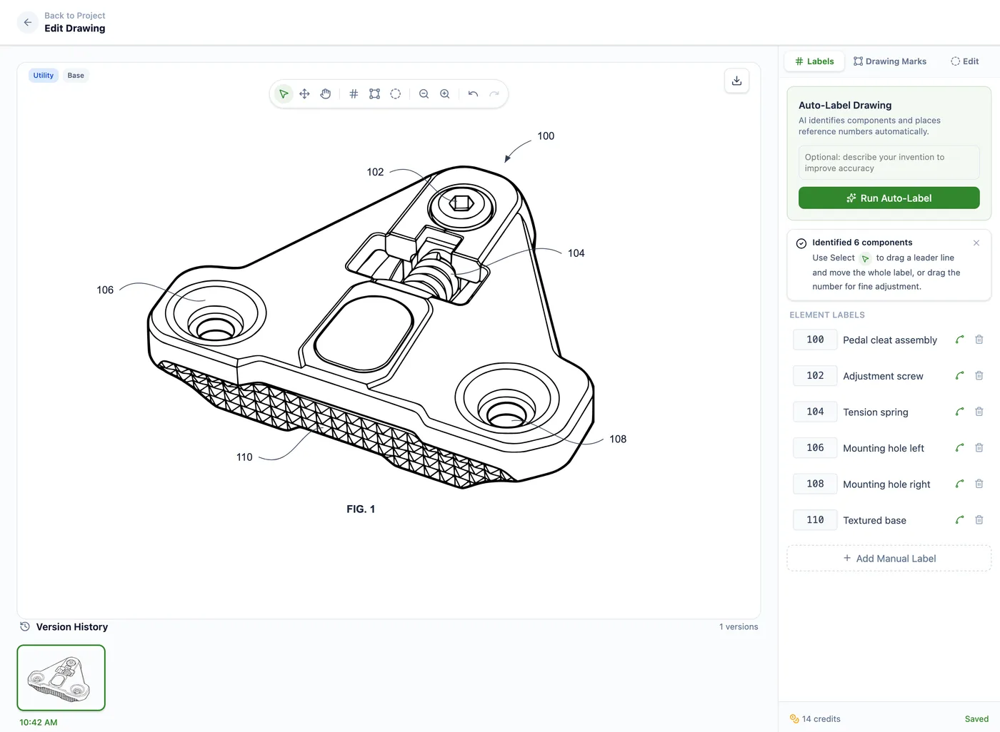
Reference Labels and Leader Lines
Auto-Label detects visible components and places numbered reference labels with leader lines. You can reposition labels, edit leader lines, and keep reference numbers consistent across the drawing set.
Clean Line-Art Preparation
The processing pipeline converts clear source images into black-and-white patent line art, cleans background artifacts, prepares vector output, and keeps the drawing legible for review and export.
Plain-English Redraw Edits
Refine figure details before labels and formal drawing sheets are finalized. Describe the change you need, such as adding thread detail, removing an unwanted feature, or thickening lines.
Figure-by-Figure Workflow
Create each needed figure from clear source images, product photos, sketches, or CAD renders exported as images. Then assemble perspective, section, exploded, detail, or flowchart figures into one filing-ready set.
Hatching and Surface-Shading Tools
Add hatching, section labels, leader lines, whiteout marks, and other vector annotations without rebuilding the drawing in a general-purpose design tool.
Sheet and Figure Assembly
Drawing Set assembly places figures onto USPTO-formatted sheets, adds sheet numbering, supports multi-figure layouts, and helps keep FIG. labels organized across the set.
Filing-Ready Exports
Export the completed drawing set as PDF, PNG, or SVG for filing review. DXF linework is also available for CAD workflows where supported.
PatentDrawingAI drawing editor
The Speed and Cost Advantage
PatentDrawingAI generates a figure in about 1 to 3 minutes. New AI drawings cost 5 credits, while Auto-Label, manual annotations, USPTO sheet assembly, and PDF/PNG/SVG export are included. That makes it useful for turning clear source images into filing-ready drawing sets without a separate illustration workflow.
Meeting each requirement by hand is where many drawing objections start. Firms that want software to handle reference numerals, formal drawing sheets, and client-matter organization can compare the best patent drawing software for law firms.
Compare Requirements Across Patent Offices
Filing internationally? See our broader patent drawing rules guide, including international considerations alongside USPTO, EPO, and PCT standards.
Generate Filing-Ready Patent Drawing Sets
Upload a sketch, photo, or CAD render. PatentDrawingAI can create filing-ready figures from clear source images, add reference labels and annotations, place figures onto USPTO-formatted sheets, and export PDF, PNG, or SVG drawing sets for review.
Generate Now, No Credit Card RequiredQuick References
Frequently Asked Questions
The USPTO may object to the drawings or issue a notice requiring corrected drawings. MPEP 608.02 explains that drawings can be required within a time period of not less than two months when they are necessary to understand the claimed subject matter. Drawing objections can delay examination and may require replacement sheets, but they are separate from whether the invention itself is patentable.
No. Under 37 CFR 1.84(a)(2), color drawings are permitted only when color is necessary as the only practical medium to disclose the subject matter. The application must include the required petition, fee, and statement. For most utility and design drawings, black-and-white line drawings remain the safer default.
There is no fixed sheet limit in 37 CFR 1.84. The practical rule is to include enough views to disclose the invention clearly without adding redundant figures. A simple mechanical invention may need only a few sheets; a software, electronics, or assembly application may need block diagrams, flowcharts, section views, and detail views.
A reference numeral is the number or character that identifies a feature, such as 10, 20, or 30. A lead line is the line that points from the reference character to the feature. 37 CFR 1.84 requires reference characters to be plain, legible, and at least 0.32 cm high. Good lead-line placement keeps the connection clear without crossing important details.
Use text sparingly. 37 CFR 1.84 allows suitable descriptive legends when approved or required, and reference characters, view numbers, and sheet numbers are expected. Long explanations, claim language, marketing labels, and component descriptions usually belong in the specification rather than inside the drawing field.
Usually, yes. 37 CFR 1.84(b) permits photographs only in applications where the invention cannot be shown adequately in an ink drawing. The rule gives examples such as crystalline structures, metallurgical microstructures, electrophoresis gels, and other subject matter where a photograph is the only practical medium. Mechanical and electrical inventions are normally shown with line drawings.
37 CFR 1.84 requires numbers, letters, and reference characters to measure at least 0.32 cm (1/8 inch) in height. A practical review step is to print or preview the drawings at reduced size and confirm every reference character remains clear. Larger, consistent labels are usually easier to examine than labels that sit right at the minimum.
The USPTO drawing rules focus on the submitted drawing, not the software used to prepare it. AI-generated drawings still need the same review as hand-drawn, CAD-generated, or patent-illustrator-prepared drawings: margins, paper size, line quality, reference characters, view coverage, and consistency with the specification.